
Introduction
The purpose is to describe the configuration of Ampron LED display communication protocol.
AmpronLED software
AmpronLED software is designed to drive and monitor the status of Ampron LED displays. Our LED display hardware and AmpronLED software together combine the solution that we define as Smart LED Display System.
Current API defines the ways of configuring and communicating with the software. The general approach, method, syntax and semantics are described in the following chapters.
The communication protocol is defined to a level of technical detail which should assure a clear understanding of how to drive, monitor and manage the software and displays.
Following is a structured in a way that at the left side you will see descriptions and at the right side are the example values.
Communication Protocol
This chapter is intended to describe the communication concept and protocol between Third Party Communication Module (TPCM) and AmpronLED software for the operational environment. The communication protocol is closely related to the configuration of AmpronLED software.
Main Communication Process:
PHASE1 - Third-Party Communication Module (TPCM) sends a control message to AmpronLED
PHASE2 - AmpronLED sends data to the Smart LED Display System (SLDS)
PHASE3 - SLDS reports back to AmpronLED with the status message
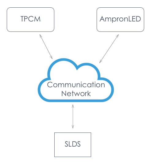
General View
The complete system is composed of the following components:
- Third Party Communication Module
- AmpronLED Software
- SLDS Display Units
- Communication Network
Third-party communication module is responsible for sending control messages and receiving status messages.
AmpronLED Software is responsible for receiving the control messages from TPCM, sending out status messages to TPCM and communicating with SLDS Unit(s).
Note: as for generalization purposes, only Ampron standard software with its communication format, syntax and semantics are described.
SLDS Display Units are the visualization units (LED displays) which provide the visual results of communication between Third Party communication module and AmpronLED software.
Communication Network is considered to include all equipment and measures between TPCM, AmpronLED and SLDS Display Units.
Method, Syntax and Semantics
Method
Messaging between TPCM and AmpronLED is performed by using HTTP GET method in both directions.
Syntax
Control message format between TPCM and AmpronLED is HTTP Request:
GET http://ipaddress:port/mlds?nameX=valueX&nameY=valueY&nameZ=valueZ
| Message element | Description |
|---|---|
http:// |
hypertext transfer protocol identifier, constant string |
ipaddress |
IP address of the server where AmpronLED Software or TPCM is installed |
:port |
communication port which is listened by TPCM or AmpronLED, integer 1025…65535 |
/mlds? |
resource request, a constant string |
nameX=valueX |
message pairs/AreaData, predefined alphanumeric pairs |
& |
separator, constant character |
Semantics
nameX = valueX - nameX is variable identifier and valueX is value of variable
There are five types of variables:
- Layouts
- AreaData
- Status responses
- Addressing
- Numbering
Please see the next chapter for details
Variables and Requests
Layouts
Layouts are configurable views of LED displays. There can be multiple layouts for every single display. However, from the communications point of view, only one layout can be defined in a single GET request.
Layouts are defined in config.json file, inside the block named “layout”.
GET http://ipaddress:port/mlds?id=GATE_2&layout=vehiclenumber&nameZ=valueZ&inumber=XXXXX
AreaData
AreaDatas are configurable sections (Areas) in every Layout. There can be multiple Areas in one Layout. From the communications point of view, if there are nameX=valueX pairs in the GET request, which are not described in the configuration file, then the request will be disregarded as faulty. If there are no pairs or fewer pairs than defined in Area configuration, the request will be handled as a request for a blank screen or blank area respectively. There are 3 types of AreaData (static text, live text and images):
GET http://ipaddress:port/mlds?id=GATE_2&layout=vehiclenumber&kiosk=21&plate=123ABC&inumber=XXXXX
Status Responses
Success
AmpronLED software confirms the successful control message execution by responding with HTTP GET.
GET http://ipaddress:port/mlds?confirm=1&inumber=XXXXX
Failed
AmpronLED software responds with unsuccessful control message execution by responding with HTTP GET.
GET http://ipaddress:port/mlds?confirm=0&inumber=XXXXX
Fault
AmpronLED software responds to the faulty command by responding with HTTP GET.
GET http://ipaddress:port/mlds?confirm=2&inumber=XXXXX
Addressing
There can be 99 MLDS units operated by one AmpronLED instance, usually, multiple instances are used:
MLDS unit identifier -> variable nameX is “id”, value is string max 255 chars
GET http://ipaddress:port/mlds?id=GATE_2&layout=vehiclenumber&kiosk=21&plate=123ABC&inumber=XXXXX
Numbering
The numbering is done by TPCM (Third Party Communication Module), AmpronLED answers with the string provided by TPCM:
Instructions sequence number -> variable nameX is inumber, value is string of reasonable length
GET http://ipaddress:port/mlds?id=GATE_2&layout=vehiclenumber&kiosk=21&plate=123ABC&inumber=XXXXX
Encoding of URL Query Parameters
Characters from the unreserved set are represented as-is without translation, other characters are converted to bytes according to UTF-8, and then percent-encoded. See Wikipedia Percent Encoding
Configuration
The main configuration is set in a config.json file. Other configuration items are defined in various files and are linked to the main file according to specific needs.
After changes to configuration, files server needs to be restarted.
Configurable Items
{
    "port": "9199",

    "displays": {
        "GATE_OUT2": {

        "displayName": "anyname",
        "displayIp": "192.168.100.100",
            "displayPort": "9551",
            "controllerType": "T430",

            "confirmIp": "127.0.0.1",
            "confirmPort": "9098",

            "displayHeight": "160",
            "displayWidth": "96",

            "layout": {
                "vehicle": {
                    "numberplate": {
                        "coordinates": "0 0 100 29",
                        "type": "text",
                "align": "center",
                        "fontSize": "24",
                        "fontColor": "255 255 255"
                    },
                    "infotext": {
                        "coordinates": "0 30 100 69",
                        "type": "static",
                        "align": "center",
                        "fontSize": "24",
                        "fontColor": "255 255 255",
                        "params": {
                            "21": "Some static text"
                        }
                    },
                    "arrow": {
                        "coordinates": "0 70 100 100",
                        "type": "image",
                        "params": {
                            "S": "fwd.png",
                            "RE": "left.png"
                        }
                    }
                },
                "message": {
                    "all": {
                        "coordinates": "0 0 100 100",
                        "type": "image",
                        "params": {
                            "WAIT": "pleasewait.png",
                            "CLOSED": "closed.png"
                        }
                    }
                }
            }
        }
    }
}
- Server listening port
- Display group name
- Display ID
- Display IP and port
- Display meta name
- Display controller type
- Feedback server IP and port
- Display height
- Display width
- Display layout
- Display areas
- Content-type
- Text-based content alignment
- Text-based content font size
- Text-based content font colour
- Picture based content parameters
Listening Port
"port": "9090",
Define the following value in config.json file:
port -> Numerical value within the range of from 1025 up to 65535
Displays Group
"displays":
displays Displays subgroup. Fixed value.
Display ID
"DISPLAYID"
The first thing to do for adding new display is defining following value in config.json file:
Display ID - String type unique value, up to 255 characters
Replace default DISPLAYID with your own unique display ID name.
Display IP and Port
"displayIp":    "192.168.200.200",
"displayPort":  "10000",
Set the following value in config.json file:
“displayIP“ -> In the form of standard IPv4 address
“displayPort“ -> Numerical value according to the specification
Display Metaname
"displayName": "anyname",
Define the following value in config.json file:
displayName -> String type value, up to 255 characters
Display Controller Type
"controllerType": "G20",
Define the following value in config.json file:
controllerType -> controller model
Feedback Server IP and port
"confirmIp": "127.0.0.1",
"confirmPort": "9092",
Define the following value in config.json file:
confirmIp -> In the form of standard IPv4 address
confirmPort -> Numerical value within the range 1025->65535
Display Size
"displayHeight":    "160",
"displayWidth":     "96",
Define the following values in config.json file:
displayHeight -> Display height in pixels
displayWidth -> Display width in pixels
Display Layout Management
    "layout": {
        "layoutName": {
            "areaID": {

                            }
                    }
                }
Define the following value in config.json file:
layoutName -> String type value, up to 255 characters
areaID -> String type of unique value, up to 255 characters
Consider the values that make sense in your overall system configuration.
Area Coordinates
"coordinates": "0 0 100 100",
Define the following values in config.json file:
coordinates -> Area coordinates in pixels (x y X Y)
x,y - square area upper left corner.
X,Y - square area lower right corner.
Area Types
"type": "static",
Define the following values in config.json file:
type -> Possible values - static, text or image
Static Text Variables
"align": "center",
           "fontSize": "24",
           "fontColor": "255 255 255",
           "params": {
                        "TEXTID": "text"
                     }
If the chosen area type was chosen static then define section texts and add following variables:
align -> text alginment. Possible values center or left
fontSize -> font size in pixels, must be smaller than area height
fontColor -> font color in RGB
params -> parameters subgroup. Fixed value.
TEXTID -> String type value, up to 255 characters
text -> Text to be displayed, up to 255 characters
Picture Parameters
"params": {
            "PICTUREID": "filename1.gif",
          }
Add following values:
PICTUREID -> String type unique value, up to 255 characters
filename.gif -> String type value, up to 255 characters filename with the filename extension.
All files must be located in the catalogue images/filename, relative to ampronled
Freetext Parameters
"align": "center",
"fontSize": "24",
"fontColor": "255 255 255"
If the chosen area type was chosen text then define following variables:
align -> text alginment. Possible values center or left. Valid only when text fits into area.
fontSize -> font size in pixels, must be smaller than area height
fontColor -> font color in RGB
Monitoring and BITE
Our information system has built-in monitoring that monitors communications to all displays that are added to the configuration file. It also monitors the successful forwarding of the information packages and has the feedback loop to a feedback IP address. Information system monitors the last sent package success. If the feedback was the same then information is not sent again. After server restart, all active displays receive the command to empty the content of the screen.
Logging
AmpronLED software logs all actions with timestamps. Logs are kept by default one month. Length may be set different according to specific needs.
Errors
Ampron API uses the following error codes:
| Error Code | Meaning |
|---|---|
| 400 | Bad Request -- Your request is invalid. |
| 401 | Unauthorized -- Your API key is wrong. |
| 403 | Forbidden -- The resource requested is hidden for administrators only. |
| 404 | Not Found -- The specified resource could not be found. |
| 405 | Method Not Allowed -- You tried to access a resource with an invalid method. |
| 406 | Not Acceptable -- You requested a format that isn't json. |
| 429 | Too Many Requests -- You're requesting too many resource! Slow down! |
| 500 | Internal Server Error -- We had a problem with our server. Try again later. |
| 503 | Service Unavailable -- Server temporarily offline. Please contact support. |
How To (Features)
Brightness control
It is possible to change the brightness of the display in 6 different ways:
1. Automatic daylight
This is the default mode, brightness is changed between 50% and 100% automatically. Time of change is defined by sunset and sunrise with an accuracy of 2 weeks, example: in the first half of May, the daytime starts later than in the second half of May and in the first half of June later than in the second half of May etc. Default sunset times are taken for local longitude and latitude.
2. Automatic daylight, specific location
With this mode, it is possible to define the sunrise and sunset times and also relevant brightness %, for each half months. To use this feature, it is needed to add a specific brightness-schedule.json file to ampronled directory (with X permissions), if the file is present then it is used, if not then default schedule is used).
3. Manual brightness for a single screen
To enable manual brightness setting feature, define the following parameter at "displayIP" level:
"sensorBrightness": true,
To use this feature send HTTP GET command to the ampronled software:
http://ampronledIP:port/brightness/VALUE?id=DISPLAY_ID
VALUE can be from 1 to 100
4. Manual brightness for all screens
To enable manual brightness setting feature, define the following parameter at "controllerIP" level to all screens:
"sensorBrightness": true,
To use this feature send HTTP GET command to the ampronled software:
http://ampronledIP:port/brightness/VALUE
5. Automatic brightness from HW sensor for a single screen
To enable automatic brightness setting from HW sensor feature, the additional hardware unit should be installed inside every screen. The ambient lighting is measured at every screen and the brightness is adjusted automatically without server interference. Relevant configuration should also be done to screen controller and in the ampronled configuration file following parameter at "controllerIP" level to all screens shall be defined.
6. Automatic brightness from separately located HW sensor or multiple sensors to all or some specific screens
To enable automatic brightness setting from single or multiple HW sensors, the additional hardware unit/units should be installed. The ambient lighting is measured at a specific location(s) compared in accordance with the defined algorithm and then the brightness information is sent to all screens or specifically selected screens. Relevant configurations must be done to ampronled configuration file and HW sensor units, as well as agreed algorithms, defined. This is usually done by Ampron technicians during the design phase.
7. Advanced automatic brightness management
It is possible to manipulate different types of data to manage the brightness of screens eg.open web RSS feeds, parsing XML, using MODBUS/TCP etc. This feature requires additional Ampron Monitoring Module hardware unit and Ampron Monitoring Software.
Configuration
Description
The main configuration is set in a config.json file. Other configuration items are defined in various files and are linked to the main file according to specific needs.
AFTER CHANGES TO THE CONFIGURATION, THE FILE SERVER NEEDS TO BE RESTARTED FOR CHANGES TO TAKE EFFECT
Configurable Items
- Server listening port
- Display group name
- Display ID
- Display IP and port
- Display meta name
- Display controller type
- Feedback server IP and port
- Display height
- Display width
- Display layout
- Display areas
- Content-type
- Text-based content alignment
- Text-based content font size
- Text-based content font colour
- Picture based content parameters
{
    "port": "9199",

    "displays": {
        "GATE_OUT2": {

        "displayName": "anyname",
        "displayIp": "192.168.100.100",
            "displayPort": "9551",
            "controllerType": "T430",

            "confirmIp": "127.0.0.1",
            "confirmPort": "9098",

            "displayHeight": "160",
            "displayWidth": "96",

            "layout": {
                "vehicle": {
                    "numberplate": {
                        "coordinates": "0 0 100 29",
                        "type": "text",
                "align": "center",
                        "fontSize": "24",
                        "fontColor": "255 255 255"
                    },
                    "infotext": {
                        "coordinates": "0 30 100 69",
                        "type": "static",
                        "align": "center",
                        "fontSize": "24",
                        "fontColor": "255 255 255",
                        "params": {
                            "21": "Some static text"
                        }
                    },
                    "arrow": {
                        "coordinates": "0 70 100 100",
                        "type": "image",
                        "params": {
                            "S": "fwd.png",
                            "RE": "left.png"
                        }
                    }
                },
                "message": {
                    "all": {
                        "coordinates": "0 0 100 100",
                        "type": "image",
                        "params": {
                            "WAIT": "pleasewait.png",
                            "CLOSED": "closed.png"
                        }
                    }
                }
            }
        }
    }
}
Define different play-styles
It is possible to define different playstyles for areas. The functionality comprises of two features, "dispEffect" and "clearEffect".
dispEffect defines how the text enters into the area while clearEffect defines how it leaves eg. text enters from up to down and leaves the area from down and up again. there are 15 different entry and exit effects which can be combined.
To enable different playstyles, define following parameters under "text" area in configuration file:
"dispEffect":"VALUE1", VALUE1 - 1...15"clearEffect":"VALUE2", VALUE2 - 1...15
VALUE1 and VALUE2 can be different
Define text colour
For "text" and "static" areas, it is possible to define font colour also with the GET request.
http://ampronledIP:port/mlds?id=DISPLAY_ID&layout=LAYOUT_NAME&AREA_NAME=HELLO&fontColor[AREA_NAME]=0_255_255
where 0_255_255 is the colour of the text in RGB
Set and change scroll-speed
Define parameter:
"scrollSpeed": "VALUE", VALUE - 0...8, 0-fastest and 8-slowest
if the parameter is not defined then default scroll speed is 4
Set text background colour
It is possible to define the background colour of "text" and "static" areas text.
To set the background colour of text, define the following parameter under the relevant area:
"backgroundColor": "0 255 255", whereas "0 255 255" is the color of text background in RGB.
It is also possible to define an alpha channel for this feature, "backgroundColor": "0 255 255 127", whereas 127 is alpha channel value 0...127
Windows command line options
Usage: ampronled-mlds-2.1.35-win.exe [options] [command]
Commands:
start [options] - Start server.
test - Testing.
Options:
-h, --help output usage information
-V, --version output the version number